自制操作系统(CoolOS) - 切换到保护模式并连接C语言
Posted

BIOS是启动在实模式下的,但是实模式限制比较多,所以接下来需要切换到保护模式。而且,接下来的操作系统可不能全部用汇编来写,那会累死的,需要用点稍微高级点的语言,那就是C语言。接下来需要做的就是切换到保护模式,并连接C语言。
修改bootloader
先把之前的hello_world.asm修改为boot_loader.asm,然后进行修改。
我们的bootloader放在了第一个扇区。后面的代码需要放到后面的扇区,因为第一扇区空间有限。但系统启动的时候BIOS只会读入软盘的第一个扇区,也就是bootloader到0x7c00。后面的扇区BIOS是不会自己读入的,所以需要我们自己读入后续扇区到内存。
先在代码最前面定义一个NUM表示将要读取80个扇区到内存。
NUM EQU 80 ; the number of sector we need to read
接下来就应该读取扇区数据到内存了。
首先将ES设为0x0820,意思就是将扇区数据读到内存的0x0820位置。因为0x7e00~0x9fbff都是可以自由使用的,大约有600kb左右。然后告诉计算机从0柱面,0磁头,2号扇区(扇区号码从1开始,也就是没有0扇区这种东西)。使用DI来记录我们已经读取了的扇区数目。
; Read data into memory from floppy
; ES:BX=where the data will.0x7E00~0x9FBFF is free to use.
; So,set ES to 0x0820,set BX to 0x0.
; Reference: http://wiki.osdev.org/Memory_Map_(x86)#Overview
	MOV		AX,0x0820
	MOV		ES,AX
	MOV		CH,0			; cylinder number=0
	MOV		DH,0			; head number=0
	MOV		CL,2			; sector number=2,read from second sector.
	MOV		DI,0			; record the number of sector we have read
每次只读一个扇区(AL=1)。并且,如果读取出错,就将出错的次数记录在SI中,并尝试重新读取,如果出错次数超过5次,就打印出错信息。
; Loop
readloop:
	MOV		SI,0			; Use SI to record the number of read errors for every sector.reset to 0 when read a new sector.

; Read data
read:
	MOV		AH,0X02			; Read sector into memory
	MOV		AL,1			; Read just 1 sector
	MOV		BX,0			; Read into ES:BX
	MOV		DL,0x00			; drive number=0
	INT		0x13			; Read sector into memory.Reference: http://www.ctyme.com/intr/rb-0607.htm
	JNC		next			; If no error,read next sector
	ADD		SI,1			; the number of read error +1
	CMP		SI,5
	JAE		error			; if the number of read error=5,print error message.

; reset disk system
	MOV		AH,0X00
	MOV		DL,0x00			; Drive 00
	INT		0x13
	JMP		read			; retry
每读完一个扇区,就将ES加上0x20,读取下一个扇区。并且软盘每个柱面只有18个扇区,两个磁头,所以在不断的读取过程中,必须注意调整柱面号、磁头号。当读取的扇区数达到所需数量(NUM)就停止读取,并打印读取成功的信息。
; next sector
next:
	ADD		DI,1			; increase the number of sectors we have read
	CMP		DI,NUM
	JE		success			; if enough,jump to fin
	MOV		AX,ES
	ADD		AX,0x20
	MOV		ES,AX
	ADD		CL,1			; next sector
	CMP		CL,18
	JBE		readloop		; A cylinder just have 18 sector,if CL>18,next head
	MOV		CL,1
	ADD		DH,1
	CMP		DH,2
	JB		readloop		; just have two head,if DH>=2,next cylinder
	MOV		DH,0
	ADD		CH,1
	JMP		readloop
完整代码在我的**Github**上。
切换到保护模式
接下来的汇编代码使用AT&T语法(对,就是那个据说很奇葩的语法),和C代码一样,使用gcc进行编译。
首先,我们需要包含一个头文件mmu.h。这个头文件定义了x86的内存管理单元(memory management unit),其实我也看不大明白,不过里面都是一些宏定义。不管了,先用着,往后再说。该头文件参考自**mmu.h**。
#include "mmu.h"
然后,先定义几个地址值,待会用来存储屏幕显示信息。
#define LEDS			0x0ff1
#define VMODE			0x0ff2
#define SCRNX			0x0ff4
#define SCRNY			0x0ff6
#define VRAM			0x0ff8
切换显卡显示模式
	# set video mode.VGA,320x200x8bit,256-color
	# Reference: http://www.ctyme.com/intr/rb-0069.htm
	movb	$0x13,%al
	movb	$0x00,%ah
	int		$0x10

	#save video info
	movb	$8,(VMODE)				# 8-bit,256-color
	movw	$320,(SCRNX)
	movw	$200,(SCRNY)
	movl	$0x000a0000,(VRAM)		# Reference: https://en.wikipedia.org/wiki/Video_Graphics_Array#Addressing_details

	# get keyboard shift status
	# Reference: http://www.ctyme.com/itr/rb-1756.htm
	# Bit(s)  Description
	#  7	  Insert active
	#  6	  CapsLock active
	#  5      NumLock active
	#  4      ScrollLock active
	#  3      Alt key pressed (either Alt on 101/102-key keyboards)
	#  2      Ctrl key pressed (either Ctrl on 101/102-key keyboards)
	#  1      left shift key pressed
	#  0      right shift key pressed
	movb	$0x02,%ah
	int     $0x16
	movb	%al,(LEDS)
显卡有多种显示模式,每种模式的分辨率、颜色种类不同。有字符模式和图像模式,字符模式只能显示字符,图像模式可以显示图像。可以使用BIOS来实现显示模式的切换(int 0x10,参考**interrupt 0x10**)。这里,我们使用320x200x8的VGA模式,分辨率为320x200,256色(8bit),使用0xa0000~0xaffff内存段控制图像的显示(参考**VGA**)。设置完显示模式后,将显示信息保存在内存的0x0ff2~0x0ff8位置,以及使用BIOS的int 0x16服务获取键盘状态,并保存在内存的0x0ff1位置。
开启A20
在8086时代,内存的地址线是只要20根的,也就是可以表示1M的内存空间,但CPU内部的寄存器都是16位的。为了产生20位长度的地址,也就产生了我们所使用的段地址:偏移地址的地址表示方式。那么问题来了,这种地址表示方式不仅仅只能表示1M的地址空间。这种地址表示方式所能表示的最大地址的表示为0xffff:0xffff,很明显,这个地址已经超出1M了,它所表示的是1M再加上64KB-16bytes的位置。8086当时的做法是,如果所表示的地址超过了1M,那就将超出的部分给反转到内存的低地址位置,称为wraps around。而且,当时的很多16为程序都使用了0xffff:0x0f~0xffff:0xffff的地址表示法。恩,好像没啥问题。但是,后来有了80186、80286…,地址线不再是20根了,0xffff:0x0f~0xffff:0xffff表示的地址也不再会被反转到低地址了。那么,那一堆程序不就不能跑了么,对,这是个巨大的BUG。然后呢,Intel想了个办法,那就是可以禁用第21根地址线,也就是A20。这样,禁用A20后,原理的反转又可以实现了。那么,问题又来了,怎么控制呢?再搞个控制器来控制?不划算。那就用8042键盘控制器吧(然而和键盘没半毛钱关系)。
但是呢,现在已经是21世纪了,估计也没有跑8086那个时代的程序了吧。为了之后能正常地使用全部内存(如果不开启A20,就算切换到保护模式,所能访问到的内存是不连续的,详细可以google),我们需要开启A20。
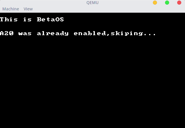
首先,让我们先来检测一下A20是否被开启了吧。因为有的BIOS是会默认开启A20的。如果BIOS已经帮我们开启了A20,那就不用再开启了。
# Function: check_a20
#
# Purpose: to check the status of the a20 line in a completely self-contained state-preserving way.
#          The function can be modified as necessary by removing push's at the beginning and their
#          respective pop's at the end if complete self-containment is not required.
#
# Returns: 0 in ax if the a20 line is disabled (memory wraps around)
#          1 in ax if the a20 line is enabled (memory does not wrap around)
check_a20:
    pushf
    push	%ds
    push	%es
    push	%di
    push	%si

	# disable interrupt
    cli

	# set es to 0
    xorw	%ax,%ax
    movw	%ax,%es

	# set ds to 0xFFFF
    not		%ax
    movw	%ax,%ds

	# store 0x0000:0x0500 and 0xffff:0x0510 to stack
    movw	$0x0500,%di
    movw	$0x0510,%si

	movb	%es:(%di),%al
    push	%ax

	movb	%ds:(%si),%al
    push	%ax

	# set 0x0000:0x0500 to 0x00,0xffff:0x0510 to 0xff
	movb	$0x00,%es:(%di)
	movb	$0xff,%ds:(%si)

	cmpb	$0xff,%es:(%di)

	# restore 0x0000:0x0500 and 0xffff:0x0510
    pop		%ax
	movb	%al,%ds:(%si)

    pop		%ax
	movb	%al,%es:(%di)

	movw	$0,%ax
    je check_a20__exit

	movw	$1,%ax

check_a20__exit:
    pop		%si
    pop		%di
    pop		%es
    pop		%ds
    popf

	ret
检测的大致原理就是看高于1M的地址表示是否被反转了,反转了就说明没有开启A20,反之,则说明已经开启了A20。这里就不详细解释了,详细可以看代码,或者看**这里**。
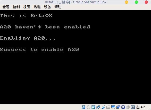
如果A20还没有被开启,就需要先开启A20:
# Enable A20:
#   For backwards compatibility with the earliest PCs, physical
#   address line 20 is tied low, so that addresses higher than
#   1MB wrap around to zero by default.  This code undoes this.
#
# Reference(8042 controller): http://wiki.osdev.org/%228042%22_PS/2_Controller
# Reference(A20 line): http://wiki.osdev.org/A20_Line#Enabling
enable_A20:
	pushf						# store flag
	cli

# There are four methods to enable A20
# methods 1:

	# disable keyboard
	call	a20wait_write
	movb	$0xAD,%al
	outb	%al,$0x64

	# read controller output port
	call	a20wait_write
	movb	$0xD0,%al
	outb	%al,$0x64

	call	a20wait_read
	inb		$0x60,%al
	push	%ax

	# write controller output port
	call	a20wait_write
	movb	$0xD1,%al
	outb	%al,$0x64

	call	a20wait_write
	pop		%ax
	orb		$2,%al						# set a20 gate to 1
	out		%al,$0x60

	# enable keyboard
	call	a20wait_write
	movb	$0xAE,%al
	outb	%al,$0x64
开启A20有多种方法,我所找到的有4种,上面用的是最长的那个代码。另外三种可以看我Github上的完整代码,其中,后面两种方法为Fast A20。上面代码的原理为,先禁用键盘,然后读控制器的输出端口,更改A20 gate为1,然后将更改后的数据写到控制器输出端口。在读写控制器时,需要先等待控制器输入/输出缓冲区为空。详细可参考**A20 Line - OSDev Wiki**和**“8042” PS/2 Controller - OSDev Wiki**。
在我测试的过程中,我发现,QEMU的BIOS是默认开启A20的,Virtualbox的BIOS是默认不开启A20的,详细看图。
QEMU:
VirtualBox:
保护模式切换
直接上代码:
# Switch from real to protected mode.  Use a bootstrap GDT that makes
# virtual addresses map directly to physical addresses so that the
# effective memory map doesn't change during the transition.
switch_to_protected:

	cli

	lgdt    gdtdesc					# load gdt info into gdt register(gdtr)
	movl    %cr0, %eax
	orl     $CR0_PE_ON, %eax
	movl    %eax, %cr0
切换保护模式前,要先禁用中断,然后加载GDT,然后将cr0寄存器的PE位(Protected Mode Enable)置为1。GDT是啥?看**这里**。上面的lgdt指令其实就是将GDT的信息加载到GDTR寄存器中,GDTR寄存器长48位,前16位为GDT的长度,后32位为GDT起始位置。所以,我们的GDT定义如下:
# Bootstrap GDT
	.p2align 2                          # force 4 byte alignment.2^2

# temporary gdt
gdt:
	SEG_NULL							# null seg
	SEG(STA_X|STA_R, 0x0, 0xffffffff)	# code seg
	SEG(STA_W, 0x0, 0xffffffff)	        # data seg

gdtdesc:
	.word   (gdtdesc-gdt-1)                 # sizeof(gdt) - 1
	.long   gdt                             # address gdt(base address)
这里定义了三个段,NULL段、代码段、数据段。
接下来,需要初始化一下,然后调用C函数:
# Complete the transition to 32-bit protected mode by using a long jmp
# to reload %cs and %eip.  The segment descriptors are set up with no
# translation, so that the mapping is still the identity mapping.
	ljmp    $PROT_MODE_CSEG, $protcseg

.code32                     # Assemble for 32-bit mode
protcseg:
	# Set up the protected-mode data segment registers
	movw    $PROT_MODE_DSEG, %ax    # Our data segment selector
	movw    %ax, %ds                # -> DS: Data Segment
	movw    %ax, %es                # -> ES: Extra Segment
	movw    %ax, %fs                # -> FS
	movw    %ax, %gs                # -> GS
	movw    %ax, %ss                # -> SS: Stack Segment

	# Set up the stack pointer and call into C.
	movl    $start, %esp
	call bootmain
先是一个长跳转指令ljmp,为什么要用长跳转指令呢?因为切换完模式后,需要重新加载CS和IP,只有长跳转、长调用、长返回能重新加载CS,这里使用长跳转。然后,初始化一下寄存器,设置一下堆栈指针寄存器SP,调用C函数bootmain。
现在,保护模式切换就圆满完成啦。
C语言
先上代码:
void init_screen(int);

//called by bootasm.S
void bootmain(void)
{

	init_screen(-1);

	//Infinite loop
	while(1)
	{
		asm("hlt"); //inline assembly
	}
}

//init the screen
void init_screen(int color)
{
	char *ptr;//pointer

	//if color=-1.....
	if(color==-1)
	{
		//vram(0xa0000~0xaffff).
		//Reference: https://en.wikipedia.org/wiki/Video_Graphics_Array#Addressing_details
		for(int i=0xa0000;i<0xaffff;i++)
		{
			ptr=(char *)i;
			*ptr=i&0x0f;
		}
	}
	else
	{
		for(int i=0xa0000;i<0xaffff;i++)
		{
			ptr=(char *)i;
			*ptr=color;
		}
	}
}
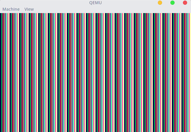
这段代码干嘛了呢?先设置屏幕显示,根据参数设置屏幕背景色,如果参数为-1,将屏幕背景设置为条纹。背景的设置其实就是更改内存0xa0000~0xaffff的值,每个字节对应一个像素,每个像素可以有256种颜色。然后,就是一个无限循环。其中asm("hlt")称为内联汇编。
Makefile
# Author: si9ma
# Blog: http://www.coolcodes.me

# Img file we will use to boot
IMG=CoolOS.img

# detect architecture for qemu Smartly.
ifeq ($(shell uname -m),x86_64)
	QEMU=qemu-system-x86_64
else
	QEMU=qemu-system-i386
endif

CFLAGS = -O -Wall -Werror -m32

LDFLAGS=-m elf_i386
addr=0xc400

img:boot_loader.bin kernel
	@dd if=/dev/zero of=$(IMG) count=2880 bs=512 			# Create a empty img file with size 2880*512 bytes
	@dd if=boot_loader.bin of=$(IMG) bs=512 conv=notrunc	# add boot_loader.bin to the first sector of img file(use conv=notrunc)
	mkdir -p floppy
	sudo mount -o loop $(IMG) floppy -o fat=12
	sudo cp kernel floppy
	sudo umount floppy
	rm floppy -rf

boot_loader.bin:
	nasm -f bin -o boot_loader.bin boot_loader.asm

kernel:bootasm.o bootmain.o
	ld $(LDFLAGS) -N -Ttext $(addr) -o $@.out $^
	objcopy -S -O binary -j .text $@.out $@

bootasm.o:bootasm.S
	gcc $(CFLAGS) -c -o $@ $<

bootmain.o:bootmain.c
	gcc $(CFLAGS) -Os -c -o $@ $<

run:
# Update img file firstly.
	make img
	@$(QEMU) -drive file=$(IMG),if=floppy

clean:
	@rm -f *.bin $(IMG) *.o *.out kernel
测试
执行:
make run
运行结果:
注:完整代码在我的**Github**上
参考
[1]Control register - Wikipedia [2]Video Graphics Array (VGA)- Wikipedia [3]BIOS-INT 10H: Video Services [4]“8042” PS/2 Controller - OSDev Wiki [5]A20 Line - OSDev Wiki [6]A20 line - Wikipedia [7]A20地址线 - 如烟海的专栏 - CSDN博客 [8]GDT,LDT,GDTR,LDTR 详解,包你理解透彻 | 技术部落 [9]mit-pdos/xv6-public: xv6 OS [10]zchrissirhcz/osask-linux: 《30天自制操作系统》在Linux下的实践